details, testing, & performance of my CNC Router
|
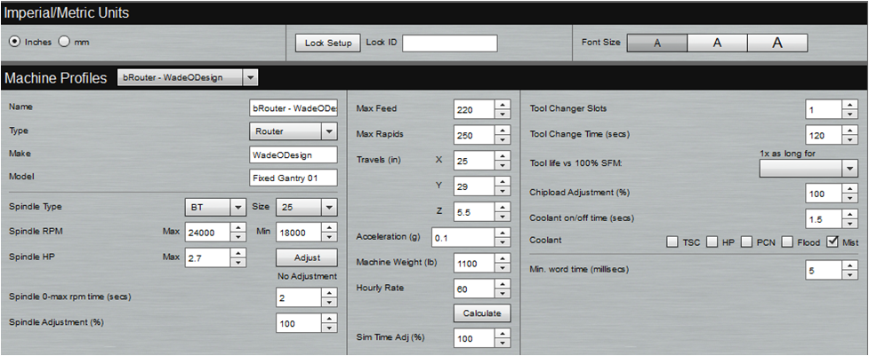
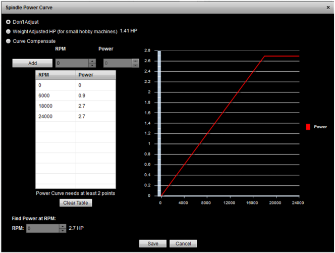
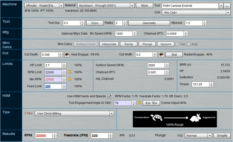
As I use my machine the past couple months I realize I have a knowledge gap when it comes to setting speeds and feeds for a particular cut. I use G-Wizard software to determine the settings and then typically modify the output with the tortoise/hair slider bar because I ‘feel’ the machine can’t handle that setting or ‘think’ it won’t produce a good surface finish. The problem is that I don’t have a good enough knowledge base in machining nor in this particular machine to make these judgments. In addition, I don’t think I’ll be able to gain this knowledge easily as I only use the machine intermittently in a hobby sense which would take forever to develop a knowledge database on cut history. So my end goal in the testing outlined in this post is to develop an understanding of when my structural machine components deflect enough under load to cause performance issue in the cut. Another way to say this is to study my machine rigidity/stiffness based on the input of my spindle power. The resultant of the test will then be used to adjust/limit the spindle HP rating in G-Wizard software to produce overall more accurate feeds and speeds for my particular machine. I’ll be referring to the G-Wizard software developed by CNCCookbook along with some relevant article from that site. First off let’s take a look at the G-Wizard machine setup for my particular router. Notice that my Spindle HP Max is set to 2.7 HP, working envelope entered in as 25”x29”x5.5”, and a Machine Weight of 1100 lb. There is three ways to refine the performance of the machine. First is to simply set the maximum HP and leave it along. Second and third you’ll need to click on the “Adjust” button in the Spindle HP column which will bring up the following options. You’ll notice that 2 additional options are presented in this popup window. The “Weight Adjusted HP” option will task G-Wizard software to estimate an adjusted HP based on the weight and working envelope sizes you entered on the main machine. The “Curve Compensate” option will use the spindle power curve data (if you have it) to adjust the feeds and speeds data. As you can see I have a 2.7 HP spindle and G-Wizard is suggesting an adjustment of 1.41 HP for the weight adjustment option. The actuality of the machine limiting performance is someplace in between 1.41-2.7 HP and I hope to determine that in this test. Before I go any further I have to say that if you still have interest at this point you must head over to CNCCookbook and read up on the articles related to this topic – it’s packed with invaluable information and I simply cannot do this subject justice myself. This post is simply to walk you through my method and show you some results for my particular machine (plus video of the event of course). So the main article from CNCCookbook which got my butt in gear to perform this test was “Set up G-Wizard for Small CNC Machines”. After reading this post I had a brief correspondence with the author Bob Warfield and he helped clarify some key points for performing this test. In particular this test should focus on machine rigidity so we want to avoid any other influences which might lead to performance issues – any good test should attempt to remove all extraneous variables. To achieve this we want proper chip clearing, good lubrication/cooling of the tool, minimized tool deflection, and to hopefully avoid any natural resonance characteristics of the machine. I’ll use a 1/2” two flute TiAlN coated end mill in a profile milling operation straight along a piece of aluminum. I’ll keep the cut width set to 40% of the cutter diameter and only vary the depth of cut to gradually increase the spindle power from a low value up to the spindle maximum. Below is a screenshot from G-Wizard of the last test I’ll attempt at max spindle hp (Case #11 in table below).
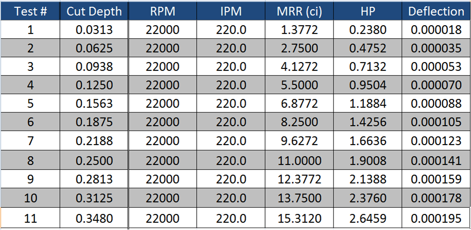
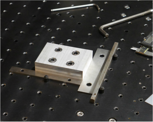
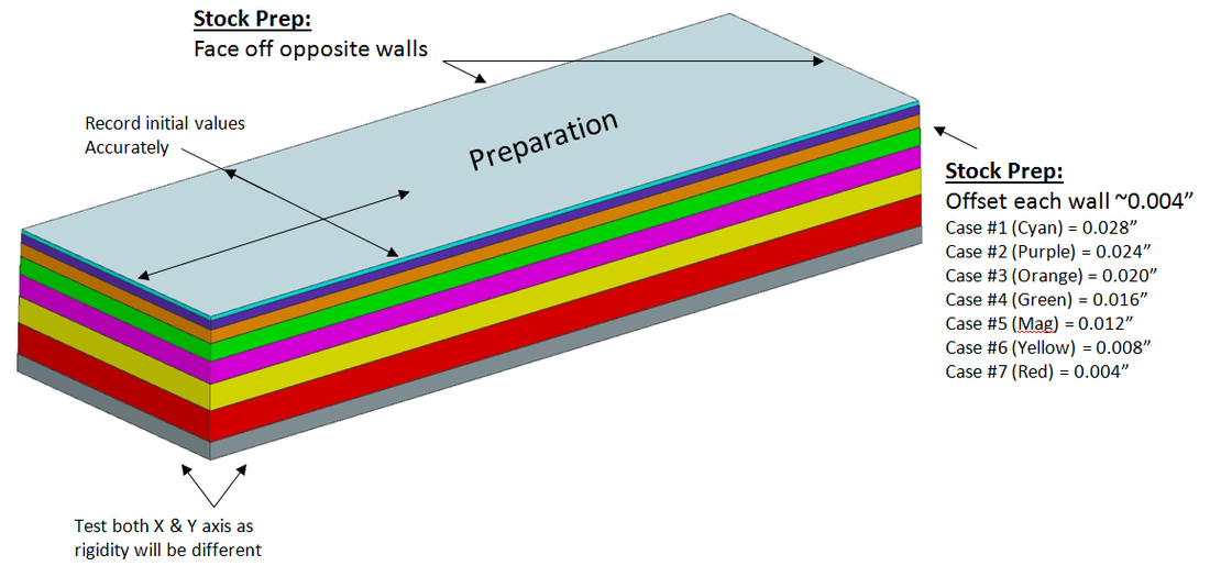
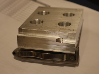
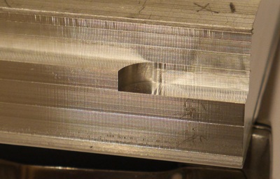
So now off to the shop… Setup is shown below. I want to make sure I have a nice big chunk of aluminum bolted down to the fixture plate securely to avoid any influence from stock deflection (thin walls) or deflection in the clamping. Again making sure to remove those pesky variables from the testing. I also ran around and made sure I had no loose connections in the machine giving all the bolts a nice tightening. Hmm … what else to consider… collet chuck tightened onto the tool, tool stickout ok, mist on. You’ll notice that I’ve placed the stock directly onto the fixture plate as this moves the spindle in the lowest position on the z-axis representing the worst case but probably typical cutting scenario. Just before starting the test I realized that I want the resultant cuts on this chunk of aluminum to give me a nice easy way to compare the surface finishes but if I simply pass at the same axis location and only increase depth I’ll potentially scuff up the previously cut surface. To remedy this I’ll need to prep the stock by creating preliminary steps of 0.004” for each test case (see figure below). In addition, after this prep step I’ll machine the opposite face square and take initial measurements. I’ll be able to squeeze in the first 7 test cases into my 1” thick aluminum stock and will take passes in both the X and Y axis. If I need to go past case #7 I’ll use the opposite side to get #8-10 and if I get to pass #11 I’ll gladly pull out a new piece of stock – unlikely. Note: After performing the test I realized this whole stepping 0.004” per test was overkill. If performing this test I suggest simply offsetting each test case by 0.001” to make sure you don’t “spoil” the previous test cut surface finish and simply live with the fact the last cut will be x thousands wider a cut (probably little impact). SANIFY CHECK and more ramblings before I start testing. I’m just about ready to perform the test and realize that I never considered using a ½” end mill to make a 0.2” wide by 0.348” deep cut in aluminum at a feed rate of 220 IPM with this machine. I really don’t think the machine can do this and will be amazed if I come close. I’ll take a guess here and set my expectations…. Well I went back to G-Wizard and setup some scenarios with different cutters which I remember entering as goals during the build – some basic setups which I used to get a feel for what I wanted the machine to do during the design phase. Most of my entries resulted in a MRR between 3 to 7 ci. Looking at my table above I’ll guess, or hope, I can do case #6 which would slightly exceed my expectations at a MRR of 8.27 ci – A half inch cutter taking a 0.188” depth of cut with 40% stepover – not too shabby for a DIY router build – we’ll see!! Sorry – I know I should simply get on with the testing but I can’t stop drawing conclusions before I start. First off I glanced back up to the table and see that case #6 has a HP rating of 1.43 – wow, that’s exactly what G-Wizard estimated HP would be for weight compensation in my router setup at 1100 lb. Is it coincidence that my initial development which used G-Wizard to estimate my expectations now matches up perfectly – probably not as I used the CNCCookbooks article “Ultimate Benchtop CNC Mini Mill” as one of my guides were in Part 4 Bob lays out this exact approach to get an initial idea for the performance you want and to help size components. OK – so I suggest simply clicking on the video before reading anything further. I’ve tried to keep everything as consistent as possible for each cut including the location of the microphone. Try to pick up on which cut should be my last attempt. Partial Conclusions – test is not complete yet: Well as you can see in the video I had issues twice now. Both times the cutter stopping had less to do with reaching the limit of spindle/rigidity and more to do with simply running into the fact that the steppers can’t handle the cut – I THINK! As I post this I’m still thinking about the whole situation and have a post over at cnczone forum to clarify if this could be a different issue. I’m fairly confident my overall machine could have taken a bit more – the surface finish looks absolutely fine to me and I didn’t hear anything spectacular which indicated an issue. The steppers seemed to be my limit. The first test at 220 IPM was actually run at 250 IPM (dumb mistake). I then modified the feed rate in an attempt to get steppers more torque. Changed to 180 IPM and got a couple more cuts out of her. The table below shows my actual test cuts from the video. I’m a bit surprised the stepper failed at about the same spindle HP input with 180 IPM then at 250 IPM. I would have expected it to perform better as the torque available at the reduced stepper RPM should have allowed a bit more headroom. So is about 1 HP my limit for the steppers? I still think I have headroom available in the machine rigidity as the surface finish looks ok to me – The pictures below show the surface finish for tests 1-4 and 6 & 7 were identical but I mistakenly took a finish pass off those cuts so you can only see in the video (no pic). I spent the entire day reviewing the stepper specifications and what type of draw on the steppers could have taken place during that cut. Looked at cutting force, current draw, and even did a test where I hooked a force gauge up the axis and measured the amount of force required to cause the stepper to stall & miss steps. The force on the gauge was about 55# while the software calculated 27# for the first stop cut – it’s a bit too close at the 220 IPM setting but somethings fishy here. If it was simply a stepper issue I would think I’d hear the whining of the missed steps which I didn’t and Mach4 became flaky after the cuts on the video which is not typical when the steppers are pushed enough to miss steps.
Maybe someone out there will indicate that the surface finish is in-fact not ok? For now, that’s all I’ve got. Will still post this and follow up later as have more information, solve this issue, or get some servos and have at it again. This test, although not the expected results, will prove very valuable if the outcome is new axis motors. As it stands this test has shown that I'm only using about 1.2 HP from the spindle and machine rigidity is holding up well. This gives me a nice justification that improvements in the axis motor will be put to good use. The question now is how much bigger do I go!
7 Comments
Arjen
9/26/2016 07:27:45 am
Looks to me like you've set a current limit to the driver and it halts the motor nicely instead of slowing it down and messing stuf up as it could me operator error or a piece working loose.
Reply
Rob
1/14/2018 07:07:06 pm
I'm surprised that the rpm calc is advising you to cut aluminum at 22,000rpm with a 1/2" end mill. My calc shows a far lower optimal speed.
Reply
6/12/2019 05:37:43 am
I've recently studied my machine and I found out that its spindle is broken. I think I'll be working with aluminum metals, so I'll try to find a supplier who can make me a custom spindle. Thanks for posting the differences in the finishes of such settings, so I'll try to use that as a guide once I manage to buy some from a good business.
Reply
Lucian
10/16/2019 07:56:31 am
Just a hint from my experience - when cutting, the vibrations are propagating to the stepper axis. At higher speeds, the steppers are very prone to resonance. So maybe the cause is that vibrations cause the steppers to stall at a much lower torque than the datasheet indicates.
Reply
Michael McMillan
3/25/2022 02:50:41 pm
When you are cutting aluminum, the cutting edge of your tool is not performing the cut, instead aluminum that you are pushing through, builds up on the cutting edge, and crystalizes, and that sharp edge performs the actual cut.
Reply
Leave a Reply. |
Archives
August 2016
Categories |

 RSS Feed