Documentation: CNC Lathe Conversion
08/21/2017: The build is complete and running! I still have a few items to complete or fix (spindle index, program fine tuning) but files are 95% accurate.
CNC Conversion Design files:
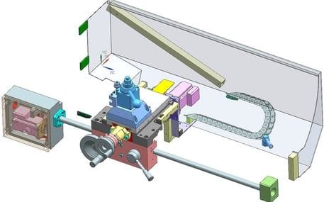
Below you can download the CNC conversion design for the 10"x22" Lathe. Simply answer the survey question to download my CAD models. See the "CNC Lathe: Design Details" section for information on the design.
|
Consider donating if you like the content - thanks!
|
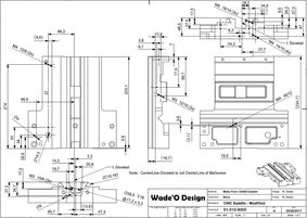
Mechanical Drawings & BOM (+price list):
|
Consider donating if you like the content - thanks!
|
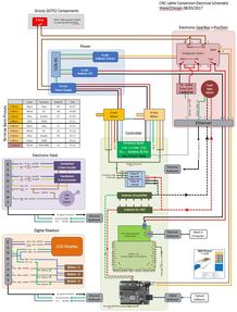
Schematics & Arduino code (code not released yet):
|
Consider donating if you like the content - thanks!
Note: The Arduino code is NOT currently available
|
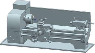
10" x 22" Bench Top Metal Lathe CAD models - "As Purchased"
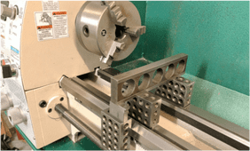
Below you can download the CAD models of the existing "as purchased" G0752 Lathe (similar to G0602). I've done my best to detail correctly the nominal dimensions of the machine but as some parts are cast and then covered with paint so expect these surfaces to have a broad tolerance. I also suspect that identical lathe models will have slightly different tolerances even on these critical parts due to adjustment allowed in the manufactures assembly process. I did spend extra time measuring the machined surfaces and critical layout features as you can see in the inset photo (measuring machined bed ways) but as a friend of mine says, "trust but verify". Some features you'll see are not complete (ie - Bed internal casting geometry) as it's not relevant to my needs. If you have any input, see errors, or want to contribute detailed models; please don't hesitate to drop me a line in the contact form. As always I ask that you answer a simple survey question to download the file because my site hosting service does not easily track downloads and I like to know the interest level.
The CAD part structure and naming convention matches the exploded views and parts lists in the manual supplied for this lathe. The manual is stamped "Mfg. Since 11/12" on all pages and indicates on the cover that it covers models 0602/0752 manufactured since 11/12 and was revised 2014. Sub-asssemblies are broken up identical to the manuals exploded view per page and I use the REF number & PART# in the cad file name. I've found that the mfg takes some freedom with part replacement (ie - my build has different length set screws and pins then the manual indicates) so in these instances I've indicated that with a REF number slightly different than the manual - I think you'll figure this out by just looking at the part names.
Oh.. and a disclaimer... I am in NO way associated with Grizzly Industrial and in fact do not even know if the CAD files are of this manufacture ... lets just say it's a of an unknown make 10" x 22" Bench Top Metal Lathe - probably Chinese :). Of course I doubt any manufacture would care much as one of the strong selling points of these hobby machines is to make your own modifications. I hope these files help your own CNC conversion efforts.
|
"As purchased" Bench Top Lathe CAD File formats in parasolid (x_t) & Step214 (stp).
|
Consider donating if you like the content - thanks!
|
Version History - CNC Conversion Design:
v0.2 - 08/21/2017
Version History - Mechanical Drawings
v0.1 - 06/22/2018 - Added all drawings
Version History - Schematic, Arduino code:
v0.3 - 06/22/2018
Version History - "As Purchase" Manual Lathe:
v0.5 - 08/21/2017
v0.2 - 08/21/2017
- Finalized mechanical design and all parts mfg and assembled ok (except spindle index wheel and mount).
- Finalized electrical design and full assembly and function ok (will post schematic with the Arduino download - soon)
- Completed the Z-axis design, limit/home switches, and cable routing. I consider this "design complete" (without electronics) and will start creating drawings and cut parts soon. Likely will have my next update mid Feburary.
Version History - Mechanical Drawings
v0.1 - 06/22/2018 - Added all drawings
Version History - Schematic, Arduino code:
v0.3 - 06/22/2018
- Updated the schematics for Arduino MEGA.
- Just the electrical schematics for now.... I'll be updating soon with other stuff.
Version History - "As Purchase" Manual Lathe:
v0.5 - 08/21/2017
- Updated .... This is as "complete" as I'll take this CAD model. All updates from here will be to incorporate contributors work.
- Completed the Apron assembly and the basic gearbox geometry.
- Changed part naming convension - see note about this in main text above.
- All the major items are present but at the moment the file only represents the geometry which is easily measured without major disassembly - this will be a long process to complete.
- Cross Slide & Carriage assy is the most complete at about 90%. The Apron will be the next assembly to get more internal detail.
- WARNING: I've triple checked the dimensions of the cross slide lead screw bracket to the saddle mounting and the cad model DOES represent my lathe BUT you'll see the position of REF # 906 (LeadScrew Bracket) needs to be located far off the tapped location of the saddle to line up the lead screw. I'm not sure if this is done for some reason or one of my parts is poorly manufactured. Would be interesting to get any feedback on this.
- v0.1 - It's just a start. I've got the Bed up to the tool post and a chuck for now.
- As I tear apart the lathe I'll add detail but this will be a work in progress.