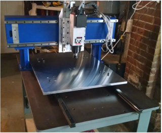
General:
Before you go too far into this article I need to warn the reader that, although my goal is to post all the information required to reproduce this machine, in no stretch of the imagination would I advise everyone to copy this exact build. The design was based on some general concepts but then guided heavily on ebay part availability and capabilities of my personal machine shop. Some purchases were good, some bad, and some redirected the design in ways I would not have preferred. This is also not a cheap build as some of the things I deemed “must haves” were over a reasonable price vs. the value added to the machine. With that said, I do believe that it may be valuable to someone looking to build a router design to machine materials tougher than woods and plastics (ie – aluminum). Any suggestions, comments, and criticisms are very welcome (Link to message board at bottom of this page).
The two main design principals I tried to achieve were stiffness and simplicity. I list these two things separately but in my view simplicity is an overreaching principle of stiffness. Yes, you can have complex machines with multiple parts achieve great stiffness but it’s typically with sacrifices. Below I’ll take you through the design in general terms and explain how these goals are realized. Some details are mentioned in the text but you’ll want to go to the 'Documentation' section for a detailed parts list, pricing (both my cost on ebay and new), and CAD/pdf files for exact dimensions and layout.
Fixed Gantry Design / Base Structure:
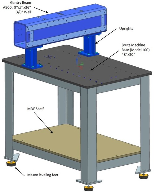
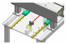
The decision on a fixed gantry design is driven by the simple fact that my primary goal is to machine aluminum and the decision to accept a limited work area of 24”x30”. This also drove the machine base, uprights, and gantry beam design to be all large steel structure. I definitely went overboard on this structure but these three items create a sound base to work from without much effort. The component sourcing achieves a welded steel structure without the welding, fabrication, and post machining overhead.
The decision on a fixed gantry design is driven by the simple fact that my primary goal is to machine aluminum and the decision to accept a limited work area of 24”x30”. This also drove the machine base, uprights, and gantry beam design to be all large steel structure. I definitely went overboard on this structure but these three items create a sound base to work from without much effort. The component sourcing achieves a welded steel structure without the welding, fabrication, and post machining overhead.
|
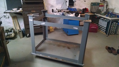
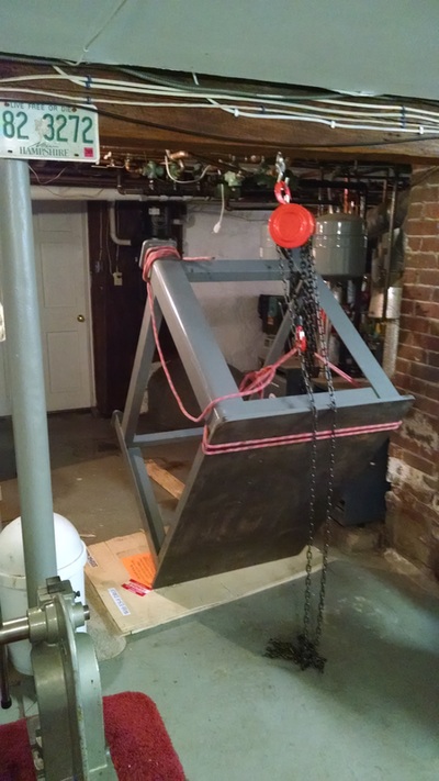
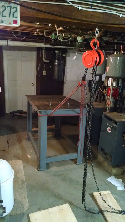
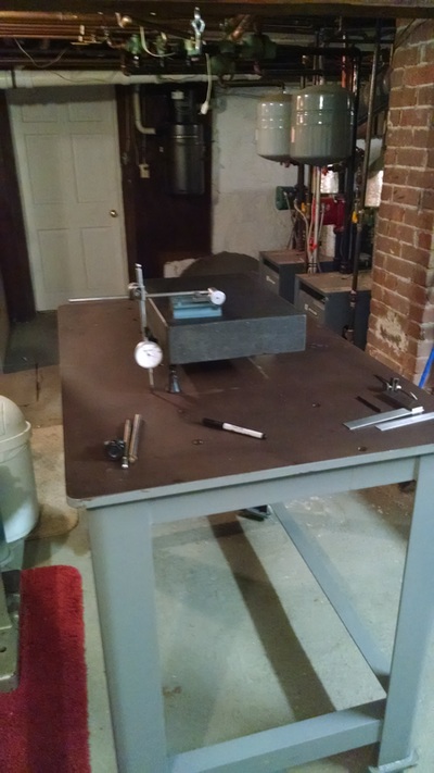
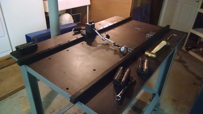
The table is something I’ve purchased before when I was a design engineer for Sylvania Lighting and always liked the quality of this part. It’s a Brute Machine Base (Model 100) made by American Grinding and Machine Co. 48”x30” by 36” tall with a Blanchard ground 1” steel top (Inter-Lakes Bases Inc. makes a similar product). The flatness of the top is 0.001” per foot cumulative and over the entire surface inspection showed a total variation under 0.002” for 48”. This gives a fantastic base for the X rails and gantry mount – no fussing around with loosy goosy adjustments – just bolt it down hard and it’s precision from the get go. Weight comes in at about 650 lb for these three parts. The base was purchased on ebay for $575 after a long waited search to get the correct size (limited by the door in my basement); I used a Mag Drill to drill the required interface holes, added a MDF board for a lower shelf, and topped it off with some Mason leveling feet. The most difficult part of the table was bringing myself to spend the $350 extra on the Mag Drill and then flipping it upright from a table down shipping position (pics below - don’t try that at home). The resulting price was $700 including shipping and this compares to new cost from Brute or Inter-Lakes of about $1300 (~$1600 with holes drilled to your specification). Overall I beat the new price and got a mag drill out of the deal. I know, still WAY too much for a router table …. But I like it! Could it be built…. Yes, but I think the cost to get the top Blanchard ground, which is a key aspect of the part, would in the end not be cost effective. These units come up on ebay about once a month and can sometimes be found in used machinery sites.
|
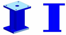
I originally designed custom uprights and planned to weld and machine them myself but ended up purchasing these parts from Misumi. If you don’t know this company it’s definitely worth a look. It’s a Japanese company established in 1963 with a USA presence since 1988. The configurable component capability, pricing, and delivery times are unmatched from my experience.
|
Price on these guys at $140 each was also more than I wanted to spend (reoccurring theme :) ) but they saved me a welding step which I wasn’t particularly excited about. I purchased without the hole pattern as I was unsure of placement at the time and simply machined these when the design was finalized along with cutting off one side of the base to fit the narrow 30" table width. They are manufactured with a 30 mm hole passing thru both ends which facilitates the electrical and pneumatic routing in a very clean manner.
|
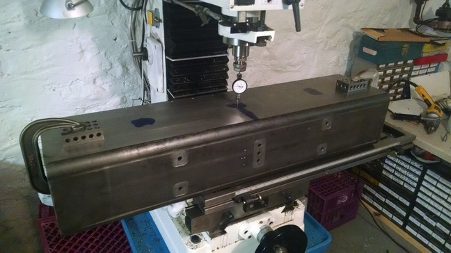
The gantry beam was by far the most difficult part to pin down and became the most challenging to machine. After looking at various welding, extrusion, and even cast options, I settled on a 9”x7”x 36” A500 structural steel tube with 3/8” wall.
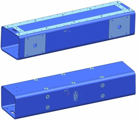
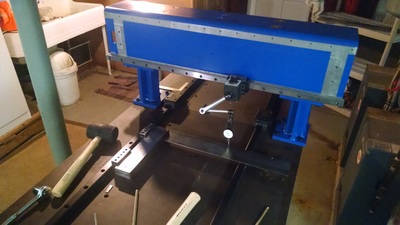
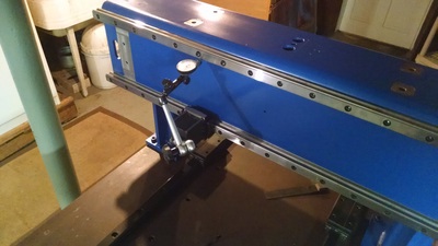
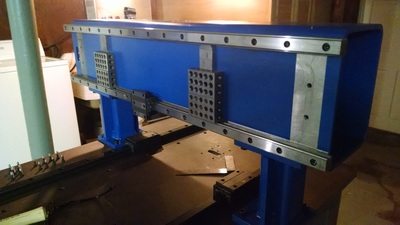
Even though the A500 form calls out this size as standard, the 9”x7” proved to be very difficult to find until I stumbled onto Totten Tubes Inc. out in California who specializes in providing ALL sizes. The 36” tube length is larger than the table width by 3” on each end which allows the Z axis assembly carrying the spindle full access to the entire cutting area in Y without needing to minimize linear rail placement for the Z axis. The tubing cost was not too bad at $120 but added shipping from California to CT brought the part cost to $200 - using a 8"x6" tube size would have been a local pickup but I wanted the extra height to give maximum spacing to the Y axis linear rails. As for machining the tube, this ended up being very challenging for my PM932 hobby mill together with my limited experience. The difficulty was that the datum interfacing to the Y rails needed to be machined flat and then the upright interfaces machined perpendicular to that datum with precision. (The light blue surfaces in the picture are machined faces). No issues for a machine with enough travel to cover the process in a single pass but I was limited to a travel of 19” with my PM-932 mill so had to setup the 36” tube multiple times. I accomplished this by providing ‘hand off’ machine surfaces (spot-faces in pictures) to help match the faces after moving and indicating the setups with OCD like determination. I used a simple HSS fly cutter to skim the surfaces and was surprised I didn’t need to take too much meat off the 3/8” thickness as the tube was surprisingly flat and square. Ended up being a great learning experience and overall the tube came out providing very accurate Y rail surfaces with respect to the table X rail interface.
So the assembly of the basic structure is quite simple with 16x M10 SHCS. If you could purchase the gantry beam already machined I think it would take about 15 minutes to assembly.
Linear Rails & Ball Screws (X & Y Axis):
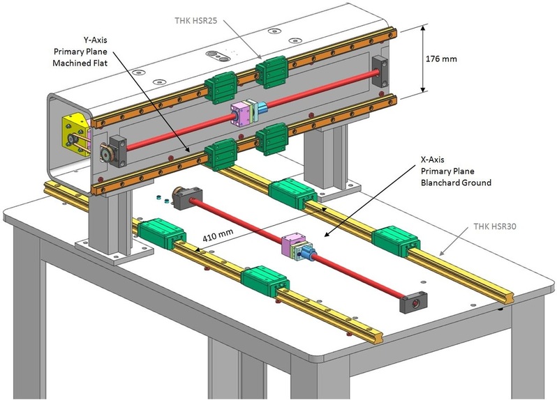
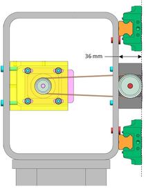
For the linear motion components of the X & Y axis the goal was to mount the rails directly to the flat Blanchard ground table and machined gantry respectively; then mount the moving mass connection plates directly to the linear rail blocks without any machined offset or additional parts. This results in a very minimal dimension in which to package the ball screw hardware. You can certainly move the ball screw assemblies outside of this narrow gap or arrange/machine clearance zones to accommodate a greater distance but the result it loss of stiffness and added complexity or machining. So a quick search for linear rail sizes determined a baseline gap for the ball screw hardware to be between 30 and 50 mm (final dimensions of this gap can be seen in the picture below). With this dimension in hand it was on to search ball screw hardware to see what could fit.
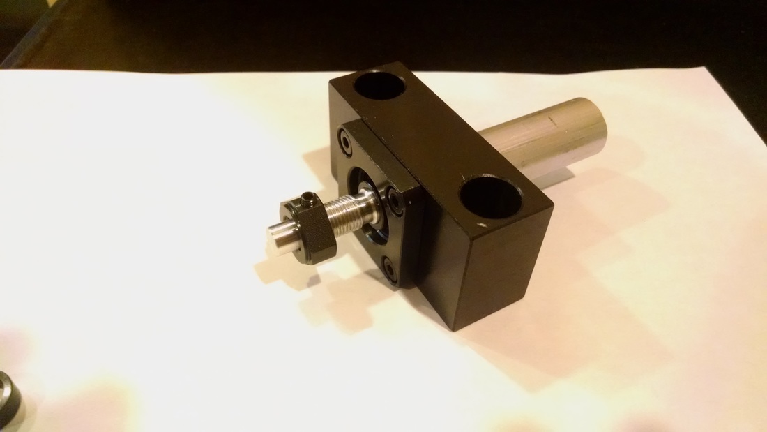
So with the largest ball screw limited by physical size, the smallest ball screws allowed is limited by speed. I estimated maximum stepper speed, and therefore shaft rotation, of 2000 RPM (update: this speed proved too high an estimate for steppers but still worked for a first pass). At 850 mm length a 12 mm OD was the smallest I could go to achieve that speed without inducing wip. Now I would have liked to use the cheap 16 mm Chinese ball screws everyone commonly uses but the size of the end supports and nut did not fit within the 30-50 mm allotted space. I therefore found a great deal on some new NSK 14 OD ball screw nuts with 4 mm pitch on ebay and purchased 4 pcs for $50 ($12.50 each) with the thought that I’d double up on each axis and build my own anti-backlash setup. The 14 mm OD screw with a 4 mm pitch gives me a potential top end rapids speed of 350 IPM at 2250 RPM motor input - my end setup will reduce this maximum to 235 IPM when ratios are taken into account (a separate post will cover this in more detail). It was off to Misumi for the end supports (fixed and support end) due to their large selection of sizes - they had a low profile version which fit the bill and packaged within a 36 mm height which now became my minimum linear rail height.
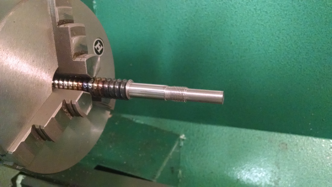
It then proved impossible over ~8 wks to find any new/used NSK rolled ball screw to match the nuts so I ended up purchasing two new 14-04 one meter length shafts directly from NSK for $110 each. Now the story goes a bit south and shows how trying to get a ‘good deal' is not always the most direct route. So the ends of the ball screws need to be machined for end supports which is typically a challenging job on a hobby lathe but not impossible…… but when you don’t have, nor planned to get a lathe, the job becomes a bit more difficult. Long story short, I purchased a Grizzly G0752 variable speed 10”x22” lathe just for this task – boy I like buying machines now :). The job proved difficult due to the case hardness of the screw shaft but in the end worked out fine once I annealed the shaft with a torch and found the right cutting tools with appropriate speeds and feeds (time to tip my cap to CNCCookbook here for the G-Wizard Calculator AND all the great information on DIY CNC including the Ultimate CNC Article). I did ask the distributor of the NSK ball screws to price machining the ends for me and the quote came back at $1600 EACH – I called and confirmed this wasn’t a typo but it was real – I consider this a No-quote and wouldn’t expect a local shop to charge anything near that.
It then proved impossible over ~8 wks to find any new/used NSK rolled ball screw to match the nuts so I ended up purchasing two new 14-04 one meter length shafts directly from NSK for $110 each. Now the story goes a bit south and shows how trying to get a ‘good deal' is not always the most direct route. So the ends of the ball screws need to be machined for end supports which is typically a challenging job on a hobby lathe but not impossible…… but when you don’t have, nor planned to get a lathe, the job becomes a bit more difficult. Long story short, I purchased a Grizzly G0752 variable speed 10”x22” lathe just for this task – boy I like buying machines now :). The job proved difficult due to the case hardness of the screw shaft but in the end worked out fine once I annealed the shaft with a torch and found the right cutting tools with appropriate speeds and feeds (time to tip my cap to CNCCookbook here for the G-Wizard Calculator AND all the great information on DIY CNC including the Ultimate CNC Article). I did ask the distributor of the NSK ball screws to price machining the ends for me and the quote came back at $1600 EACH – I called and confirmed this wasn’t a typo but it was real – I consider this a No-quote and wouldn’t expect a local shop to charge anything near that.
|
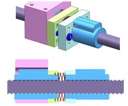
The ball screw nut connection hardware was done on my PM932 mill. At this time I only have the double anti-backlash nut assembly on the X axis and will make the comparison of its use wrt the Y axis in a separate post with potential design improvements. The double nut assy uses a Smalley wave spring at the moment ... Update Nov 2015: I've taken performance data and realize the Smalley spring does not provide enough load. I'm replacing this design with disc springs and document this change in a separate blog post here -> CNC Router Performance
|
With ball screw hardware finalized it was on to find the linear rails based now on a minimum height measurement of 36 mm with price and availability on ebay being a secondary criteria. I ended up with THK HSR25 low profile for the Y axis and HSR30 for the X and was surprised to learn that the larger series THK slides were about the same price as the smaller sizes ( I suppose due to demand). Both units fit ok in the end but the optimal size for this design was a standard height HSR25 (not low profile) which would provide just the right offset distance required to mount the ball screw hardware. The assembly of the rails and ball screws onto the machined faces was done with indicators, gage blocks, and 1-2-3 blocks to insure precise setup as seen in the below pictures.
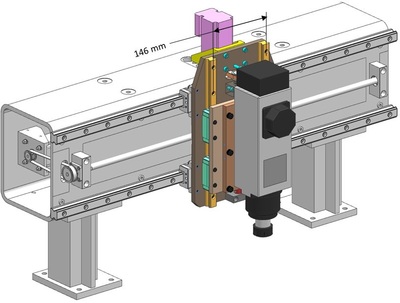
You’ll notice in the first few CAD pictures that I dimension the spacing of the linear rails as this was a point of the design I paid particular attention to. Without going into too much detail here, as this is getting much longer than expected, I’ll point you to a guide I found on cncroutersource which I found to be extremely useful which explains some guidelines when spacing the Y & Z linear rails.
|
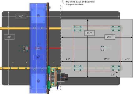
Spacing of the X axis linear rails and blocks can be seen in the top view picture. As with commercial fixed gantry CNC routers (ie - Onsrud) the X blocks are spaced inboard of the full working area to maximize travel vs. machine footprint. If the moving table is sized exactly to the outer boarders of the linear blocks (red dashed square in picture) then the base table & rail length in X would need to be exactly 2x the travel 19.3” which would result in a base table & rail length of 38.6”. Yet by extending the X table beyond the linear rail block envelope by 4.9" on each end, the travel increases to 29.1" (19.3+4.9+4.9), and the base table and linear rail length only extend 1x the added travel (19.3*2+4.9*1+4.9*1=48.4") saving about 10". Of course this then requires the table to fall outside the machine footprint at the end of stroke (see picture) but the benefit of reduced cost and overall size is still realized. Now if I was to implement a moving gantry design with this exact size table length of 48" the resulting travel would be ~36" as the spacing of the moving gantry linear blocks would eat up about 12" of the table length. So I sacrificed ~6" X travel for the moving gantry... for me a reasonable trade off for the stiffness and simplicity.
|
|
The ball screws are belt driven with NEMA 23 stepper motors from Schnieder Electric which has the drivers directly integrated into the motor housing. The motors were acquired on ebay used for a great price of ~$25 each so I figured I’d try them out. I will not say much more about the motors at this time as I’m still trying to get the communication working to the driver (they came set at 10,000 steps per rev which is too much for the RPM I want to run). The 3GT timing belt and gears are purchased from Misumi and supply a 1.5 to 1 ratio (update: the ratio was originally targeted for torque increase & speed reduction but I've come to learn this does not utilize the machine like it should... will be modifying pulleys to go 1:1 or 1.25 to 1 to increase IPM and run the steppers at lower RPMs - future blog post).
I machined the NEMA 23 motor brackets on my PM-932 milling machine. The locations of the motors are nicely tucked away inside the gantry beam for the Y-axis and under the table for the X-axis. |
Z Axis Assembly with Spindle:
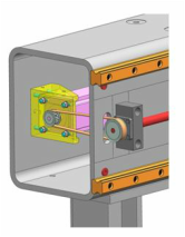
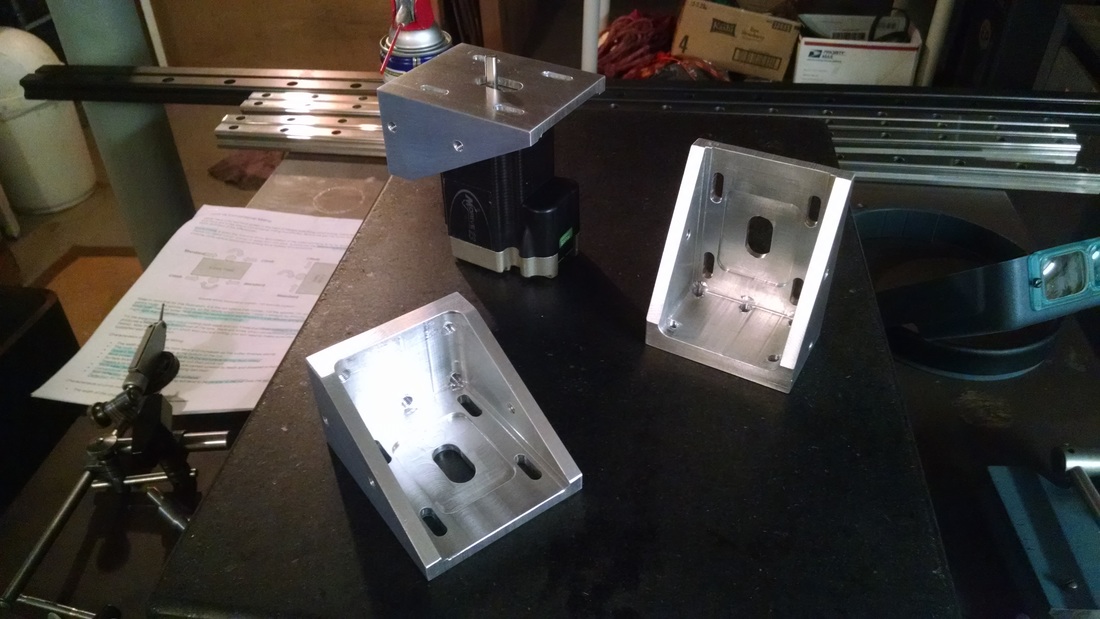
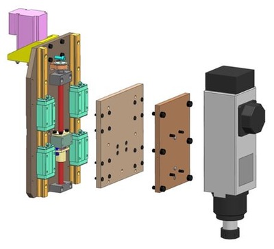
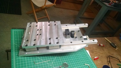
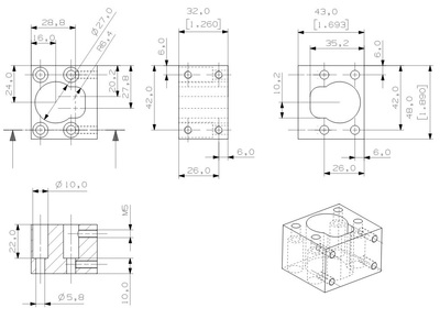
The Z axis once again uses THK linear rails HSR20 together with Misumi Lead Screw components with 12 mm OD and 2 mm pitch. Again you’ll see a double nut to eliminate backlash but I don’t have this implemented yet and will post a separate blog with comparison of results with and without this setup. The attachment plates are machined on my PM-932 milling machine out of 6061-T6 aluminum. The last attachment plate onto the spindle allows for easy tram adjustment using a single pivot pin into the intermediate plate.
The Z axis once again uses THK linear rails HSR20 together with Misumi Lead Screw components with 12 mm OD and 2 mm pitch. Again you’ll see a double nut to eliminate backlash but I don’t have this implemented yet and will post a separate blog with comparison of results with and without this setup. The attachment plates are machined on my PM-932 milling machine out of 6061-T6 aluminum. The last attachment plate onto the spindle allows for easy tram adjustment using a single pivot pin into the intermediate plate.
The spindle, the heart of any CNC, caused me much aggravation. I nearly purchased a Chinese water cooled unit multiple times but kept balancing that units cost & quality with used ebay listings for an industrial Colombo spindle. Even considered a new Colombo RS 73.2 2.2kW unit at $1620 without a VFD (am I nuts?). In the end I stumbled onto DamenCNC, a great website in the Netherlands selling a mid range industrial spindle that fit the bill very nicely. The unit is a TeknoMotor ElectroSpindel C41/47-C-DB which is made in Italy. It’s a 2.0 kW double bearing unit running on 3 phase 220V with an ER25 collet at 24000-18000 RPM. The unit I choose has a separately integrated 24VDC cooling fan which is supposed to make the unit a bit quieter & still supply sufficient cooling at lower RPMs. The unit was $900 including the fan and collet nut and I also purchased a Delta VFD for $314 (VFD022E21A 1x220V -> 3x220V 2.2kW) , VFD Brake ($35), and 75W power supply for the fan ($48). Unit came all wired with a 3 m cable to the VFD and already setup - plug and play. I’ve run it fine but no cutting at his time – will update once I get some chips flying. (update: very happy with this unit and highly suggested!)
Miscellaneous:
The moving X axis table is 23.5” x 29.25” x 5/8” 5083 Cast Aluminum purchased from MidWest Steel Supply for $160.
The moving X axis table is 23.5” x 29.25” x 5/8” 5083 Cast Aluminum purchased from MidWest Steel Supply for $160.
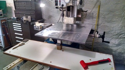
Drilling the mounting interfaces was done on the PM-932 mill and a little help from some saw horses as the plate was way too large for the mill table (see photo gallery "Overview / Gallery" from the menu). I simply used a full size print to lay out the hole locations, center punched, and then used the mill like a drill press and let the center drill find the punch locations. A jig pattern with taps and precision holes will follow once the router can perform this job.
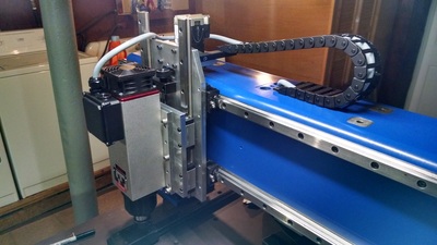
A cable tray, air nozzle, and air manifold with low flow and bypass 'blast' round out the assembly.
A cable tray, air nozzle, and air manifold with low flow and bypass 'blast' round out the assembly.
Summary:
I started this project as a hobby in Sept. '14 from a blank piece of paper and it took on many iterations along the way with machine shop purchases, machine restorations, and various other things interjected along the way. Believe it or not I only had a drill press in my basement at the start of this project (see Shop Tour to see what it's progressed to). Over 12 months I fretted over every purchase by investigating all types of alternative designs prior to making my purchase, searched endlessly on ebay for deals, and occasionally got frustrated with that process and just said 'screw it' and bought what I wanted. Believe it or not, the above process was a very enjoyable experience and what I actually want in my hobby.
A fixed gantry router is a very simple design and can certainly be done at a better price point; but as I said earlier, I wanted this machine to be as robust as possible for machining aluminum. To that end, I tried to source only high end components and was surprised at the elevated cost of these parts when compared to hobby components - you can see this in the priced BOM as I'll include both my cost (ebay etc) and the cost to buy comparable components new.
At this time the jury is still out as to the operation. I've run a ghost job to get my feet wet with CAM, G-Code, and Mach4 which ran fine but the steppers still need tuning. I'll be adding a dust shoe, install limits/stops, and likely need to place all the electronics into a better enclosure and rewire. Much work still to do but I'll be first making some cuts and testing out the operation as-is. I'll be populating the 'Special Topic Blog' section to document anything which follows after this point and I'll keep a running list of these posts below with links.
List of "Special Topic Blog" posts:
If you want to see some videos of this router in action please visit my youtube page -> WadeODesign
Hope you found this informative and useful. Thanks for taking a look. Leave message board comments by clicking on the below button or go over to a forum post I've started on cnczone and post questions there. -> Link
Cheers,
Rob
I started this project as a hobby in Sept. '14 from a blank piece of paper and it took on many iterations along the way with machine shop purchases, machine restorations, and various other things interjected along the way. Believe it or not I only had a drill press in my basement at the start of this project (see Shop Tour to see what it's progressed to). Over 12 months I fretted over every purchase by investigating all types of alternative designs prior to making my purchase, searched endlessly on ebay for deals, and occasionally got frustrated with that process and just said 'screw it' and bought what I wanted. Believe it or not, the above process was a very enjoyable experience and what I actually want in my hobby.
A fixed gantry router is a very simple design and can certainly be done at a better price point; but as I said earlier, I wanted this machine to be as robust as possible for machining aluminum. To that end, I tried to source only high end components and was surprised at the elevated cost of these parts when compared to hobby components - you can see this in the priced BOM as I'll include both my cost (ebay etc) and the cost to buy comparable components new.
At this time the jury is still out as to the operation. I've run a ghost job to get my feet wet with CAM, G-Code, and Mach4 which ran fine but the steppers still need tuning. I'll be adding a dust shoe, install limits/stops, and likely need to place all the electronics into a better enclosure and rewire. Much work still to do but I'll be first making some cuts and testing out the operation as-is. I'll be populating the 'Special Topic Blog' section to document anything which follows after this point and I'll keep a running list of these posts below with links.
List of "Special Topic Blog" posts:
- CNC Router Performance: Accuracy, Repeatability, & Backlash
- CNC Router Limit & Home Switches: Design and performance
- CNC Router Machine Enclosure: Design, Build Details, & Results
- CNC Router Fixture Plate: Design & Fabrication
- CNC Router Performance: Rigidity vs. Spindle Power - What's the Limit? (Partial Post - pending servo upgrade to continue)
- CNC Router Performance: Servo Time! Replacing my steppers. (Coming REAL Soon)
- CNC Router Drive component Performance: Calculations, Baseline results, & Improvements (Coming Soon)
- CNC Router Report Card: Evaluation of my Fixed Gantry Design, & "What improvements would I make" (Coming Soon)
If you want to see some videos of this router in action please visit my youtube page -> WadeODesign
Hope you found this informative and useful. Thanks for taking a look. Leave message board comments by clicking on the below button or go over to a forum post I've started on cnczone and post questions there. -> Link
Cheers,
Rob
Consider donating if you like the content - thanks!
