details, testing, & performance of my CNC Router
|
Two major aspects of my fixed gantry router were left incomplete prior to making a few first cuts and taking some basic performance measurements. One was the anti-backlash ball nut design, which this blog post will focus on, while the other was Home/Limit switches which will come in a later post. I’ll be updating the download section to v0.2 which will incorporate both designs above. As for the performance, my first impression of the accuracy was uplifting but the backlash was something which needed controlling. This was a bit expected because I hadn’t fully included an anti-backlash ball nut design into the x y axis. What I’ll do in this post is fully document the performance “as is” without any improvements and then step through the changes and eventually record the final performance results with respect to positioning. Test Outline: All measurements are taken with a 1” B&S Dial Indicator with 0.0005” graduations. The resolution of this indicator is ~0.00015” as I can determine positions between the graduation markers and this, as it should be, is better resolution of my positioning system which is 0.00026”. As I want to also measure backlash I will take measurements by approaching the position in both the positive and negative directions. I will then repeat the process with a load against the moving axis in both pos. and neg. directions. Motors speed will be set to 74 IPM which is 35% of rapid speed. Test01: No Load; Positioning Pos. & Neg. Directions
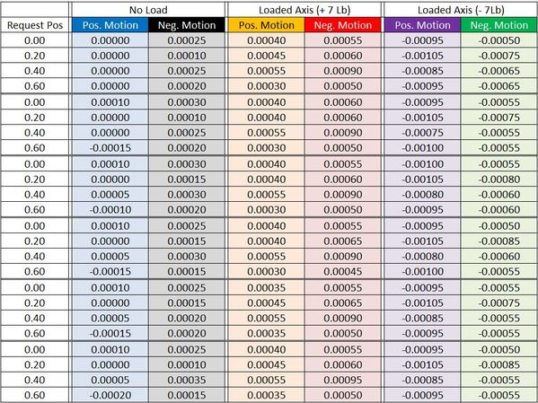
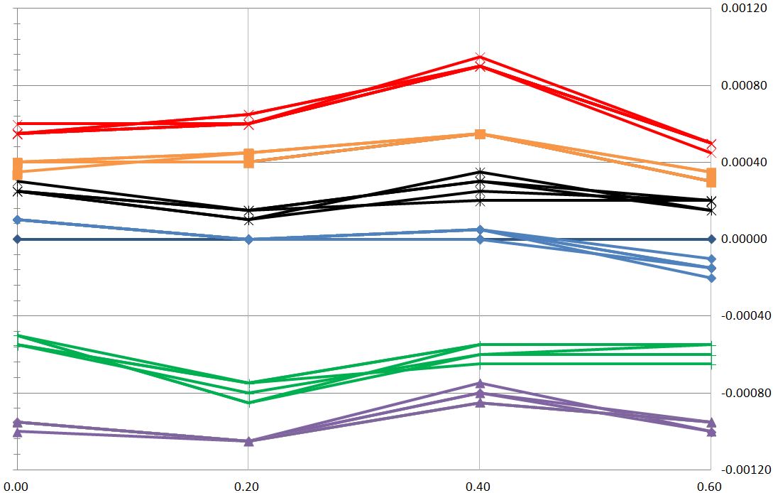
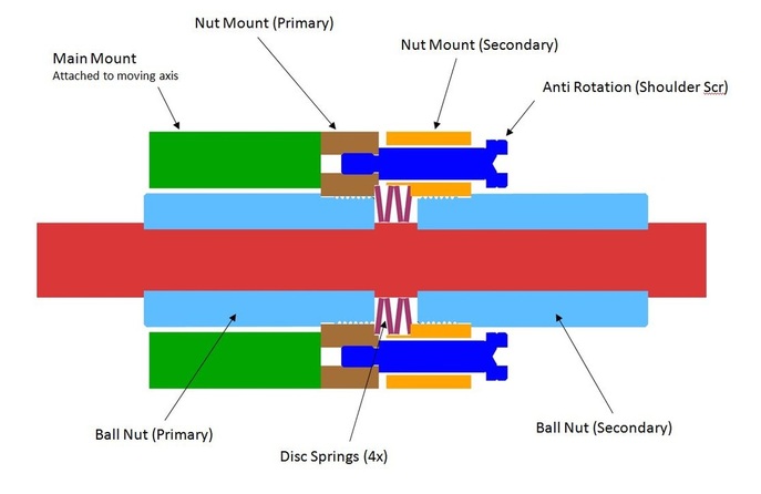
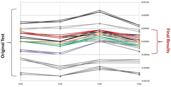
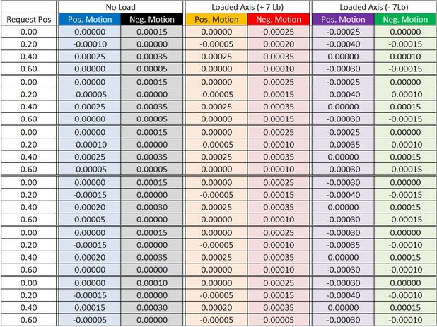
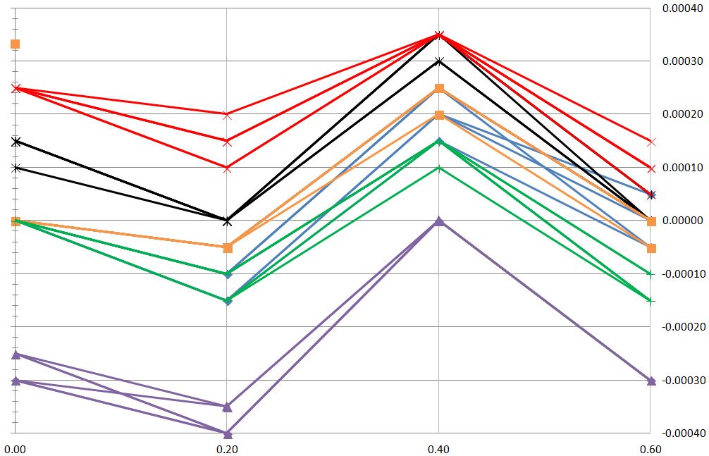
Positioning Test Results (Test01 & Test02): Table 1 – Position Raw Data (Pre Anti-Backlash) The tabular data is grouped into 3 separate tests. Blue/Black without Load, Orange/Red with a load in positive axis direction, and Purple/Green with load in negative axis direction. Graph 1 – Positioning (Pre Anti-Backlash) Conclusion (Pre Anti-Backlash): Repeatability: 0.0002” (+/- 0.0001”) Accuracy: 0.0004” (+/-0.0002”) Backlash (no load): 0.0005” (+/-0.0003”) Backlash (with load): 0.0018” (+/-0.0009”) The repeatability looks tight as expected. The accuracy of the unloaded Blue/Black set is a bit larger than expected and hopefully this comes into better control when backlash is addressed. The backlash of the Black/Blue unloaded set doesn’t look to bad at 0.0005” but when comparing a loaded positive to negative Red->Purple combination it’s quite apparent improvement needs to take place. Checking the manufacture data on this ball screw shows it’s actually within spec (0.1mm/0.004”). Note that this is a rolled general purpose ball screw from NSK. Anti-Backlash Nut Design: The axis used for the positioning data above actually has my original anti-backlash design incorporated into it using a Smalley wave spring. The load exerted between the nuts is about #10 proving to be too low and doesn’t accomplish much. The new design is shown below and will use disc springs to increase the load to about #100 +/-25. I’m using Misumi #SRBN-28-A Disc Springs which exert 1127 N (#253) over 0.6mm (75% deflection). I’ll stack 4 pieces in series and target ~30% deflection yielding #100 at a deflection of 0.96mm. As my ball screw has a 4mm lead, this results in rotating the secondary nut 90 deg to achieve the target load. At assembly I’ll need to check the orientation of the primary and secondary nuts when the disc springs start to contact and add shims behind the disc springs until the resultant angle is 90 deg. Edit 1/9/16: I finally found documentation for recommended preload on the ball nuts - both THK and NSK document this very well in their technical docs..... "The optimum preload is one third of the maximum axial load from the system. However, as an excessive preload adversely affects service life and heat generation, the maximum preload should not exceed 10% of the basic dynamic load rating (Ca) of the ball screw." So I have 3 types of loading to consider.
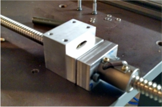
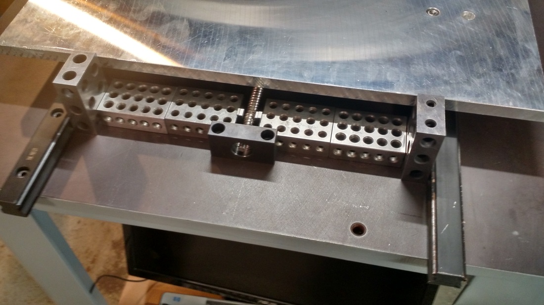
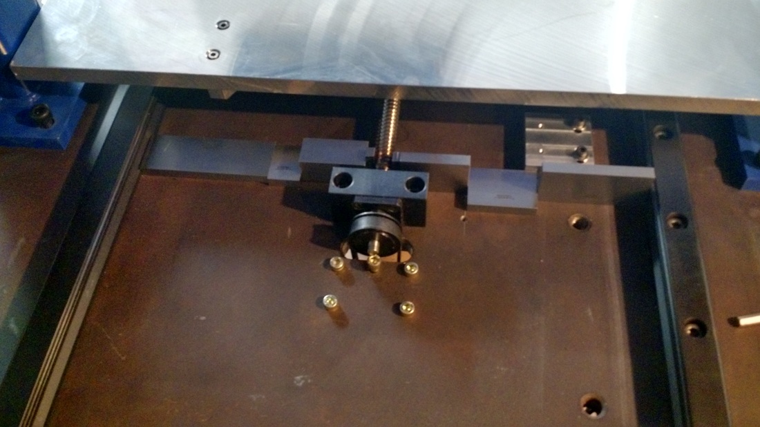
hmmm.... this may also be why I saw the top IPM feed rate drop from 190 to 170 IPM on final tuning. Off to make the new secondary mount and try out the increased load. I'll update this post with final position results soon... And back .... below is a picture of the new anti backlash assembly for the X axis (table). And before we get to the results a note on aligning the ball screw with the linear rails to insure it rides parallel to avoid any type of binding. My approach is to use Gage blocks stacked on either side of the linear rails to precisely position the ball screw to the center of the rails within 0.001". The assembly is very easy and thought worth passing along. And now for the linear positioning results with the anti backlash design installed. I repeated the exact same tests as above. First I'll show an overlay of the original test result this time colored gray with the new results in color. Graph 2 – Overlay graph, Gray=original data, Colors=With Antibacklash You can easily see the improvement on the above overlay. Below is the raw data. Table 2 – Position Raw Data (With Anti-Backlash) And the data graphed below. Note that the scale needed to be reduced to +/-0.0004 to show the plots better. That's a full range scale of <0.001" !! Graph 3 – Position Raw Data (With Anti-Backlash) Conclusion (WITH Anti-Backlash): Repeatability: 0.0001” (+/- 0.00005”) Accuracy: 0.0003” (+/-0.00015”) Backlash (no load): 0.0003” (+/-0.00015”) Backlash (with load): 0.0006” (+/-0.0003”) LOTS of zeros..... Needless to say I'm happy with the results. I'll need to ponder the results a bit and be back with some observations etc. Update 01/29/2016: One aspect I've failed to include in this post is the performance aspects of my drive system. For the above tests I was driving a 4mm pitch screw with a speed reduction ratio of 0.66 from a NEMA23 1.8 deg motor at 2 microsteps (0.9 deg per step). The resulting accuracy predicted for this system is 0.00026" (0.66 * 1rev/400steps * 4mm/25.4"). This accuracy is based on the resolution of 0.9 deg (+/-0.45 deg) of the motor only and does not take into account the screw belt etc. Results of the above test look to be spot on at 0.0003".
What's next? Well I'm a bit unhappy with the top speed I can achieve with my current setup so I'm going to be changing the speed reducer pulley setup to a speed increaser. I'll be going fro 0.66 to 1.33 ratio. This will of course reduce my positioning accuracy at the current microstep of 2. Therefore I will also be increasing the microstep setting of the motors to try and maintain the original accuracy. Luckily this was already required when I did my final tuning of the motors as I found that the X & Y axis moved more smoothly at an 8 microstep setting. It is my understanding that although you are requesting the motor to achieve lower values of resolution with microstepping you soon come to a point which the error in the motor to achieve a given step is simply larger than the resolution you've requested. As this error in step position is most commonly about 10% of a step, you can improve accuracy up to about 10 microsteps. Once you pass the 10 microstep point the improvement in step 'size' resolution is simply the same as the error in step position. So with that said, I'll be running the above test once more with 8 microstep setting and a 1.33 ratio - accuracy prediction for this setup is 0.00013" (1.33 * 1rev/1600steps * 4mm/25.4"). Wow - better accuracy with more speed? Ok... I'll be conservative here and assume that although I'll be at 8 microsteps the accuracy of my motor will be about half that. So 0.00026" which is exactly the accuracy I targeted in the begining. Results will follow - it will be curious to see if the above holds true. I hope to have the new pulleys next week and post those results around end Feb. Cheers.
9 Comments
Robert Lopez
5/15/2016 04:46:21 am
This is an amazing machine Wade. Thanks for explaining all the details. I am looking forward to what is next.
Reply
Wade
5/15/2016 06:10:45 am
Thanks RL - glad you like the router. I had the machine torn apart for the past few weeks to make upgrades to the gear ratio to increase rapids speed and make some other modifications. It's back together now so will concentrate on rewiring all the electronics into a proper enclosure. The electronics is the last project I have and then this machine will be "done". I'll post some final files, write a summary, and then move on to modeling the generic cad files for anyone who would like to build this type of machine.
Reply
Leigh
8/22/2016 04:05:49 am
Just found your channel on youtube. A huge thank you for all your work. Looking to build a cheap cnc and you have published all the info . Thank you Thank you. Wont totally copy your design but will use a lot of it. You got great results well done.
Reply
Wade
8/22/2016 09:45:53 pm
Leigh - thanks for the kind words. Good luck on your build.
Reply
Tom Skulander
5/26/2017 07:36:59 am
Hi Wade, I hope you're very pleased with this machine. As you'd admit it's not perfect and is work in progress but you've done a great job. I'd be interested to know if you had considered using NEMA 34 stepping motors. Yes they're more expensive but should have given you the safety margin in the cuts. Also the fixed gantry design is a winner if your shop has the room.
Reply
Wade, I'm not finished with this build yet (going on 3 years now I think,) But I'm getting ready to push on it again. I remain very happy with the design, and grateful to you for sharing all this information. I will be using Teknik ClearPath motors on the machine. All The Best, Paul Vogt, Kings Mountain, NC
Reply
Blouis79
10/28/2023 05:31:26 am
I read that cnc software can correct for backlash. Presumably this comes with some disadvantages but high precision ballscrews are very expensive.
Reply
Leave a Reply. |
Archives
August 2016
Categories |
 RSS Feed