The "Special Topics" blog posts focus on additional design
details, testing, & performance of my CNC Router
details, testing, & performance of my CNC Router
CNC Router Machine Enclosure: Design, Build Details, & Results (also a mist coolant system)2/6/2016 One of the first things I realized after the machine started cutting was the amount of mess created. Chips were not only flying around the shop but creating a major problem by littering the table X-axis rails and ball screw. In this post I’ll describe my recent addition to my router by detailing the machine enclosure. I’ll start with the list of requirement, get into the design, pics and video of build, and then offer some alternatives which I investigated along the way. "Enclosure" is a term used loosely here as you'll see it's not your typical containment box approach. Requirements:
OK ... enough of that. It's just that this list proved extremely helpful for me to write down as I found myself struggling to come up with a sufficient design for my specific router build. Design Details: Below you'll see the complete CAD design. It's a bit unconventional for a "Machine Enclosure" as it's split into a combination of multiple approaches. The design can be broken down into three main sections: 1) The 'conveyor' protection for the table linear rails and ball screw, 2) The rear guard/shielding, and 3) The front/spindle shields. 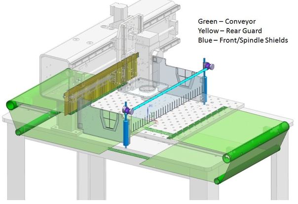 "Conveyor" Protection The protection for the X-axis Table is the odd ball design here. I haven't seen this approach used yet and as I write this post, although I'm parts complete and ready to assemble, I've yet to verified it works (fingers crossed). .... well, just ran the table with conveyor attached - works much better than expected for first try. Will post a video at the end of this post - kinda cool. You may say, "why not just mount 4 walls directly to the moving table".... First, the Y-axis gantry motion is allowed to move the spindle beyond the extent of the table which would then crash into the side walls. Ok, then make the side walls static by attaching them to the base and only attach the end walls to the moving table. I played around with this design for awhile but the drawbacks were.. a) obstructed part loading with the walls, b) used more material $ then the 'conveyor' approach, c) I didn't think I'd like the looks of the end wall on the table moving around, d) I didn't really think it wise to mount any guarding to the moving parts. So the result is a 'conveyor' design using.... ready for it.... PVC schedule 40 pipe and a window shade. A 1-1/2" PVC section makes up the two end rollers and are mounted to the base table. They don't actual roll but I'm expecting the window shade to slide freely over the PVC. As my linear rails on the X-axis table extend about 1" over the extent of the table (I was trying to utilize every last bit of material to maximize stroke), I needed to make some cutouts for the rail and truck to move to the end position. I think the roller end position will actually 'clean up' the visual appearance of the table end. A 1" PVC section is then 'slipped' into position utilizing a slot in the PVC together with the Base 1/4" leg sections. I'm expecting this sudo-mount to be enough to retain the 1" PVC in place (again does not 'roll'). As for the conveyor material, I simply had the hardware store cut a cheap $10 window shade to width and will attach 2 pieces to each end of the moving table, wrap around the rollers, and connect them with a spring for tension. Four (or more) things can go wrong here.... 1) acceleration of the table causes the conveyor belt to buckle and flap enough to cause issues, 2) the conveyor does not ride straight and possible slips off one side, 3) the tension of the belt causes too much friction between the PVC and window shade, 4) the window shade material does not hold up to the abuse from aluminum chips and continuous rolling back and forth. Time will tell. Below are some more details of the CAD design for the conveyor. 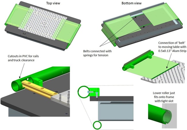 Rear guard/shielding The rear guard is a nylon conveyor stip brush (74405T9) from McMaster Carr with a compatible holder (8813T52). I'm not concerned about visual in the rear so decided to try a brush. It's a 4" long 3/16" width with diameter 0.014" general purpose nylon bristles. It's a bit stiff and I'd probably choose the 0.010" diameter if done again. Mounting is simply to the backside of the uprights and allows 2 positions of mounting, one which allows brush to lay flush with table and another 3/4" up to accommodate a thick spoiler board. The bristles will allow about 1/2" part interference to go thru the entire length ok but any higher than this and I think it may bend the aluminum mounting strip. So it will probably allow a 2" tall part at a reduced width (~4") thru without issue as the overall force from the bristles will not come from the entire length. Front/spindle shields The front shields are made up of Impact-Resistant 1/4" Polycarbonate sheet (8574K43 - blue in pics) & 0.04" thick Chemical-Resistant PVC Type I Film (87875K61 - yellow in pics) both from McMaster-Carr. The side shields have 4 magnets bonded in to allow mounting to the steel upright and post and allow quick removal. It also has a cutout where a single piece of film is bonded which allows the spindle to pass. The main front shield film is mounted to a 3/8" rod which is then attached to a vertical 1"-3/8" post mounted into the table with a 3/8" universal clamp to allow adjustment and quick removal. I should be able to remove all the front shields in <30 seconds for cleanup etc. 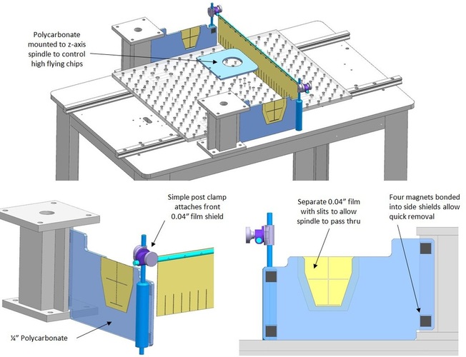 Below slideshow has some pics of the final results and in process manufacturing ....... and below that is a youtube video of the 'conveyor' in action. Update 4/1/2016: I have cut multiple parts and below is some observations and things I might change if doing again.
Added a Mist Coolant system: I absolutely needed to add a mist system - spraying wd-40 from a can was not fun. I just happened to have purchased 2 Wesco mist systems at an auction some time ago on the cheap to I went about to use as much hardware as possible from one of these units to make a custom mist to fit my router build. The Wesco mist unit works by delivering compressed air and mist to the nozzle tip with two small separate tubes which run through the braided sleeve. The mist is then mixed with compressed air only after it exits the nozzle tip - this can be seen in photo below - focus on the brass tip end of the nozzle. A flow valve controls both compressed air and fluid independently with a manifold block which I mounted onto the z-axis. The close proximity of this flow manifold to the exit nozzle allows fast response to flow changes. To position the nozzle I opted for a small Noga model NF1033 articulated holder which has 51mm and 56mm arms. At $75 bucks this is not a very economical solution for holding a mist nozzle but I've wanted to pick up one of these small Noga arms for the shop anyway, so "two birds". The unit comes with a 360 deg fine adjustment base attached with a dovetail to a permanent magnet which is all removed to expose a simple M6 thread to mount directly to the spindle column mounting bracket on the router. The NF1033 also comes with a 3/8" clamp holder on the business end which fits the Wesco misting nozzle perfectly. Below are some in photos showing the original Wesco mist unit and the modifications to adapt this to the router. The articulating arm of course moves the nozzle into position with ease and locks to exact location. The reach of the arm allows the nozzle to be located around the spindle about 270. I opted to replace the original Wesco SS coolant tank with a simply 2 liter plastic bottle which is located on the base and out of sight behind the gantry. The elevation of the coolant for this style mist unit must be below the nozzle outlet to avoid dripping when compressed air is removed and I also found that placing the tank too far below the nozzle (on the floor of the base) created too much lag time to get the mist flowing and operation was sporadic.
0 Comments
Leave a Reply. |
Archives
August 2016
Categories |
 RSS Feed