The "Special Topics" blog posts focus on additional design
details, testing, & performance of my CNC Router
details, testing, & performance of my CNC Router
|
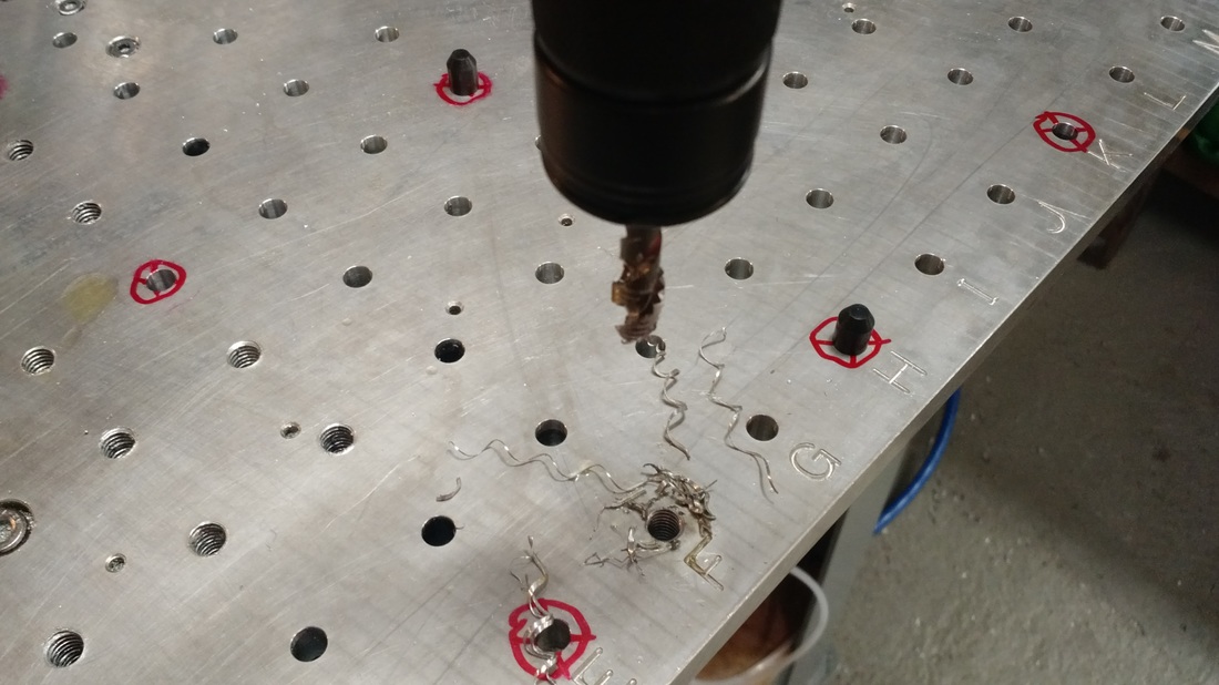
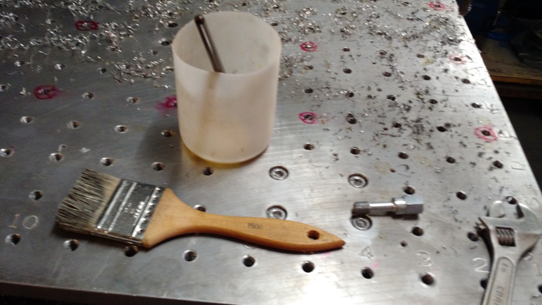
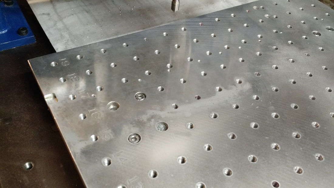
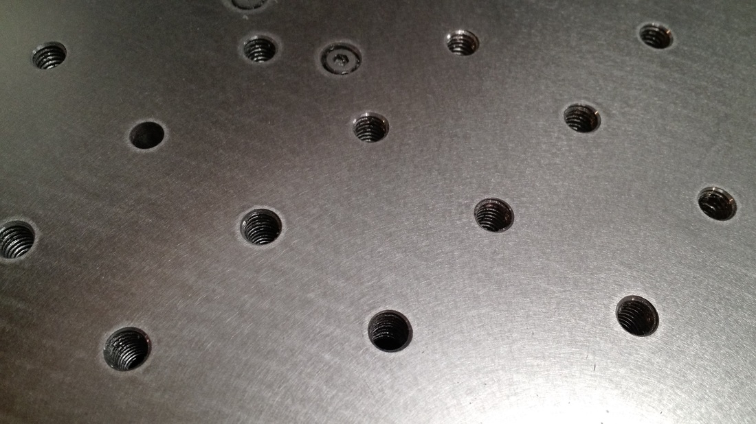
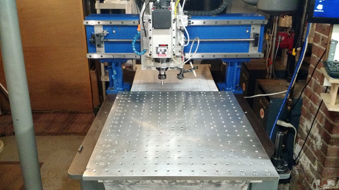
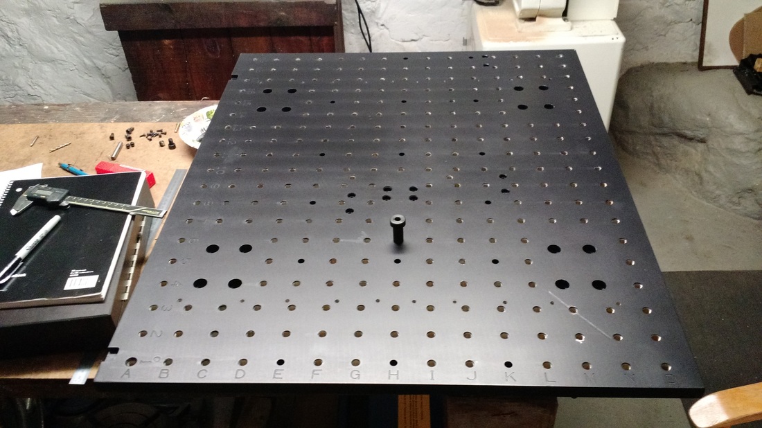
The design of the router fixture plate went through a few iterations in my mind and during this time I've left the plate a simple solid aluminum table and mounted all my jobs up to this point onto an MDF spoiler board attached to the plate. I've done this because I don't have much experience in part setup, the use of CNC machines, nor the use of CNC software to locate parts and wanted to first get a feel for how a fixture plate can best be used prior to drilling a bunch of tapped holes. In this post I'll walk through each aspect of "how to setup and start a job" on a CNC router and explain my decisions and final design. Warning: This post if filled with my assumptions without extensive experience running a CNC machine.. Also of note is the fixture plate is 5083 Aluminum 29" x 23.5" x 0.63" at a cost of $161 from MidWest Steel & Aluminum. First, the simple operation of finding, and then more importantly re-finding repeatably, a zero location for the X & Y axis.. I was very surprised to see that my simply toggle type limit switches which double as home switches in Mach4 are re-finding the absolute machine zero position with a repeatability of under 0.001". BUT I don't have extensive data yet and still don't trust them so will likely still use some very accurate mechanical switches which I purchased specifically for finding home (once Mach4 and/or the smoothstepper get there act together with home offsets). These switches do not actuate from the ramp angle of the stop block as the toggles do which eliminates a point of error, are connected to the structure in a stiffer manner, and cost ~$75 bucks vs the toggle switch $7 (not sure how this cost is justified but I'll assume it's something otherwise I'm just a boob). This has given me a high level of confidence that the absolute machine position can be found, and re-found from cold start, emergency stops, etc. In addition to that confidence gained, I've specifically located the switches to actuate and read zero at a location which I feel most of my part setup will coincide with. Further, at this zero point, my ball screw nut is at the very end of travel along the screw shaft and at the motor drive end so as not to worry about thermal growth of the shaft influencing the zero from a cold to warm machine. It's surprising how much a ball screw nut location along the screw shaft can be effected by thermal growth during operation. THK lists 5 deg Celsius variation during operation, dependent on loading, which results in 0.002" over a meter - not drastic but why not simply design out the error when finding zero. I've tried to show this last point in the picture below focusing on the table axis but all 3 axis are set up with the same approach. 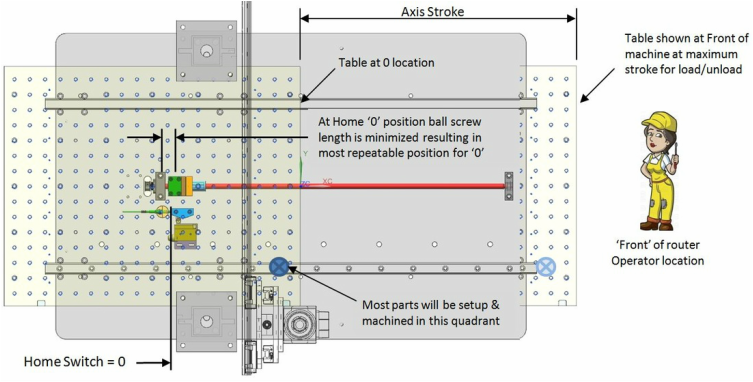 Second, I want the fixture plate to play an accurate role in the router operation. This is not simply a wood spoiler board and will have accurate machined holes which I want to use to confidently locate a job (same as a vise on a mill). Therefore the fixture plate must have a relationship to the previous step of finding machine zero in an accurate and repeatable way - not to mention squareness to the linear motion. To this end I've machined two pocketed features into the fixture plate to create accurate edges which will represent the X/Y axis zero point of the fixture plate and together will allow me to 'tram' the plate along the table motion axis. To find the edges I'll use an electronic edge finder ($25 bucks) as my typical spindle speeds are simply too fast for a traditional edge finder (thing freaks out at very high RPM). The resulting offset of these edges to the machine absolute zero found by the limit switches will then become my home offset entered into Mach4 to set the starting machine (or work) zero upon startup. Now I expect that in the beginning I'll verify the location of the fixture plate zero to the software zero with the edge finder on a regular basis but expecting this operation to eventually be a periodic maintenance check. Now that the software, via the electrical switches, can repeatably find the fixture plate location and orientation properly it's time to drill some holes. Of course the hole pattern on the fixture plate will be located relative to the machined pocketed edges to the best ability of the machine I have available for such a large part... which of course is my router. So now to the grid pattern I've chosen. First up is the tapped holes which I'll be using 3/8"-16 threads to match the set of hold down tooling I already have from the mill. I'll be spacing the threaded holes on a 1.5" grid with some locations missing due to the linear rail mounting locations from below. I'll also be substituting 17 of these locations with a 5/16" precision hole to be used for accurate location of subplates (CarrLane CL-3-RP, CL-3-DPX) or used as edge alignment features. I'll be adding a precision 0.500" precision counterbore feature to 31 of the threaded holes to be used together with a shoulder bolt (CarrLane CL-32-SS) for semi-accurate locations... not sure if this is useful yet. Two independent 3/8"-16 outside the standard grid are required to allow mounting a 4" Kurt vise which I have. And lastly I'll be engraving letters and numbers along the axis. 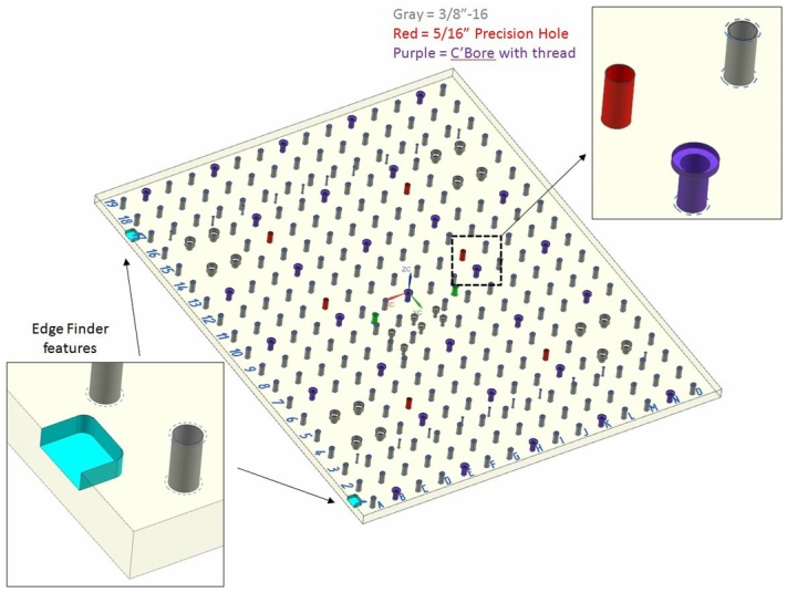 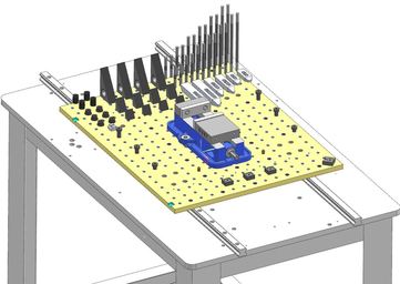 I've started off with a set of already owned 3/8"-16 standard hold down clamps and added to this a set of CarrLane 'Tiny Vise Edge Clamps' CL-6-TVR & CL-6-TV. The below picture shows the current hardware I'll be using to setup jobs onto the fixture plate including the Kurt 4" vise, pins, etc as mentioned above. Update 8/7/16: The standard hold down clamps shown in the figure have proved to cause issues with machining around the edges of parts due to the height of the clamp above the part - the spindle collet and mist nozzle start to interfere with machining path. I've since purchased some more CarrLane parts to remedy this situation by attempting to utilize a low profile side clamping hold-down. Part were a bit expensive but I think will be worth the cost.... CarrLane part numbers CL-15-SAC and CL-10-SAC. Machining: I used a 3/16" carbide 2 flute end mill to helical mill the 3/8" tapped and precision holes to a 0.3025" diameter with a 5.5 ramp angle. I then used a 0.3135" carbide reamer on all these holes running it at 1800 RPM and 10 IPM. I had to use carbide because my spindle had 0 hp with the RPM required for a HSS reamer. I thought even with a carbide reamer I'd have issues at 1800 as this is way off the charts for this spindle (calculated 0.3 hp at 1800 RPM) but it went rather well without the spindle getting warm at all as it has an electric fan cooling. Engraved letters and numbers along the edge of the plate was done with an Amana Tool 45733 60 deg carbide engraving bit. As for tapping the 3/8" holes...... Believe it or not this operation took over 3 weeks!! I planned to use a Micro-100 TM-250-16 carbide thread mill and although it took some time to figure out the programming it worked beautifully .... FOR 5 HOLES !!!.... before it snapped the bit. At $65 bucks I wasn't about to try this technique again, didn't even care what I could have done better, and immediately started to hand tap the holes. Got about 15 holes done the first night... back at it for 15 more the following day, and then woke up the next morning and had debilitating back pain! I hate tapping - always have and know the twisting motion isn't good for an already deteriorated disc situation. So 4 days on my back to think about the alternatives. I couldn't use the router spindle for ridged tapping because of the low torque available at the required RPM in addition to not really knowing the exact RPM to match with z axis feed as it has a VFD. I considered purchase of a Tapmatic for the milling machine but the plate is simply too large to put on the mill and the cost of these units is quite high. So.... I ended up purchasing an Articulating Tapping Arm - and LOVE IT! The catalyst came from a video blog by NYCCNC covering the Flexarm A-32 unit but I couldn't justify the cost of this production unit in a hobby shop. I ended up buying a 'budget' unit new off Ebay (also available on Amazon) made in England by "Machine Tapping" and distributed by SRA in MA (exact unit at this Link). There are other low cost options on ebay but I think this unit is superior at $999 as it comes complete with a full set of ANSI clutch tapping collets and allows the head to pivot 90 deg (the Chinese models on ebay do not have either of these items or come with ISO collets - watch out as these don't match american purchased taps both inch and metric). The unit runs fantastic and the flexibility to use all around the shop will generate far more use than a Tapmatic type chuck for me. I currently have the unit mounted directly to the router base and it has full range to cover the entire Fixture Plate and a nearby vise. As the unit can be simply lifted off the mounting post I'll likely add additional posts at the mill and the workbench and move this tapping arm to wherever I need it. I was impressed with the quality of this unit including the tapping collets and pneumatic driver and would certainly recommend if a grand is burning a hole in your pocket - or you hate tapping as much as me. The only thing I can say slightly negative about this unit is that it sucks the air down rapidly - it works so we'll that you want to keep the button depressed, immediately start tapping the next hole, and with my little 30 gallon reciprocating compressor this simply isn't possible (2 holes then pause about 60 seconds). Below image gallery shows some in-process manufacturing of the plate and some shots of the tapping arm. Some parting thoughts:
Rob
2 Comments
Leave a Reply. |
Archives
August 2016
Categories |


 RSS Feed